![]()
Products


We are actively taking measures to improve product quality levels.
Applications


Why Hamamatsu?
Support


Our company


Investors


Japan (EN)
Select your region or country.
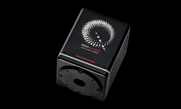
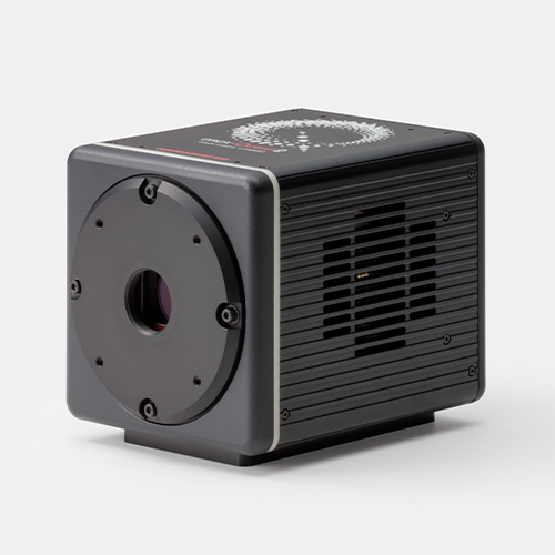
ORCA-Quest IQ qCMOS camera
C15550-23UP
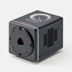
Power new discoveries: ORCA®-Quest IQ is a high-performance and flexible camera for every researcher.
The ORCA-Quest IQ inherits the ORCA-Quest series’ core features—low noise, high resolution, and high quantum efficiency. The new feature of Camera Link output allows the camera to support advanced applications such as quantum technology, adaptive optics and super-resolution microscopy. These applications require a control system through a Camera Link interface for image acquisition, processing, and high-speed feedback to peripheral devices.
ORCA is a registered trademark of Hamamatsu Photonics K.K. (China, EU, France, Germany, Japan, UK, USA).
qCMOS® is a registered trademark of Hamamatsu Photonics K.K. (China, EU, Japan, UK, USA).
Features
- Readout noise (typ.): 0.30 electrons (rms) at ultra quiet scan
- Effective number of pixels: 4096 (H) × 2304 (V)
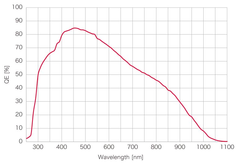
- Quantum efficiency: 85 % (peak QE at 460 nm)
Frame rate: Camera Link Standard Base/Full Configuration
Camera Link, with a history dating back to the early 2000s, uses LVDS (Low Voltage Differential Signaling), which is highly resistant to electrical noise. This standard offers high reliability and stable operation even in noisy environments, and is still widely adopted in many frame grabber boards and image processing equipment. ORCA-Quest IQ supports base/full configuration standards to meet the various needs of our customers.
Base Configuration *1*2
| Binning | X (pixels) | Y (pixels) | Frame rate (frame/s) |
|---|---|---|---|
| 1 × 1 | 4096 | 2304 | 7.19 |
| 2048 | 2048 | 16.1 | |
| 1024 | 1024 | 64.7 | |
| 512 | 512 | 259 | |
| 256 | 256 | 1030 | |
| 256 | 4 | 19 800 | |
| 2 × 2 | 2048 | 1152 | 28.7 |
| 4 × 4 | 1024 | 576 | 115 |
Full Configuration *1*3
| Binning | X (pixels) | Y (pixels) | Frame rate (frame/s) |
|---|---|---|---|
| 1 × 1 | 4096 | 2304 | 28.7 |
| 2048 | 2048 | 64.7 | |
| 1024 | 1024 | 259 | |
| 512 | 512 | 532 | |
| 256 | 256 | 1040 | |
| 256 | 4 | 19 800 | |
| 2 × 2 | 2048 | 1152 | 115 |
| 4 × 4 | 1024 | 576 | 120 |
*1: When using the Camera Link output function, camera control is limited to USB 3.1 Gen1.
*2: Single Camera Link cable connection.
*3: Dual Camera Link cable connection.
Evolution from ORCA-Quest
The ORCA-Quest IQ is a qCMOS camera that inherits the core features of the ORCA-Quest series, low noise, high resolution, high quantum efficiency, and introduces a new Camera Link output.
For details on the camera’s core features, please refer to the ORCA-Quest 2 qCMOS camera page.
Camera articles
qCMOS camera vs. EM-CCD camera vol.1 – Performance comparison of Photon counting cameras
This article will guide you in choosing the best photon-counting camera for your application.

qCMOS camera vs. EM-CCD camera vol.2 – Qubit state detection
This article explores how cutting-edge CMOS cameras can be leveraged for qubit state detection in quantum computing.

Applications
Neutral atom, Trapped ion
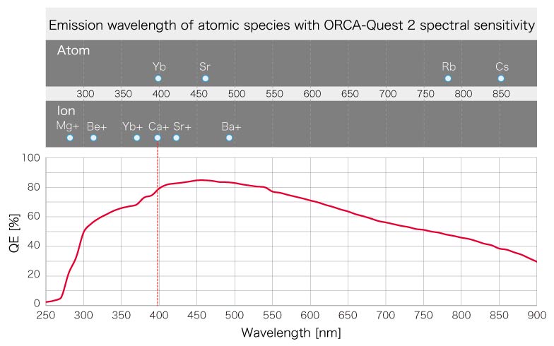
Neutral atoms and ions are aligned one by one in an array to be utilized as Qubits for Quantum computing. The qubit states can be determined by observing the fluorescence emanating from each of them. As the measurement of fluorescence needs to be completed in a short time period, photodetectors with very low-noise and high-speed are required. ORCA-Quest 2 can do both the diagnosis of the whole qubit array and the state detection of each qubit with very low noise characteristics and high-speed readout. Also, the QE covers a wide range of wavelengths for major ion and atom species.
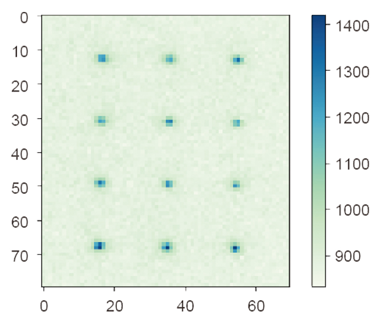
Fluorescence imaging of Rb atom array with ORCA-Quest
Data courtesy of Prof. Takashi Yamamoto and Associate Prof. Toshiki Kobayashi, The University of Osaka
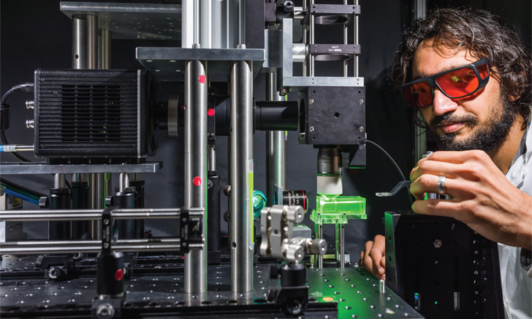
Quantum optics
Quantum optics uses single photon sources to make use of the Quantum nature of the single photon. There is a growing demand for photon number resolving detectors due to their applications in quantum optics research, to accurately distinguish photon numbers entering the detector. A photon counting camera, a new concept in camera technologies, is expected to make a new discovery in this field.
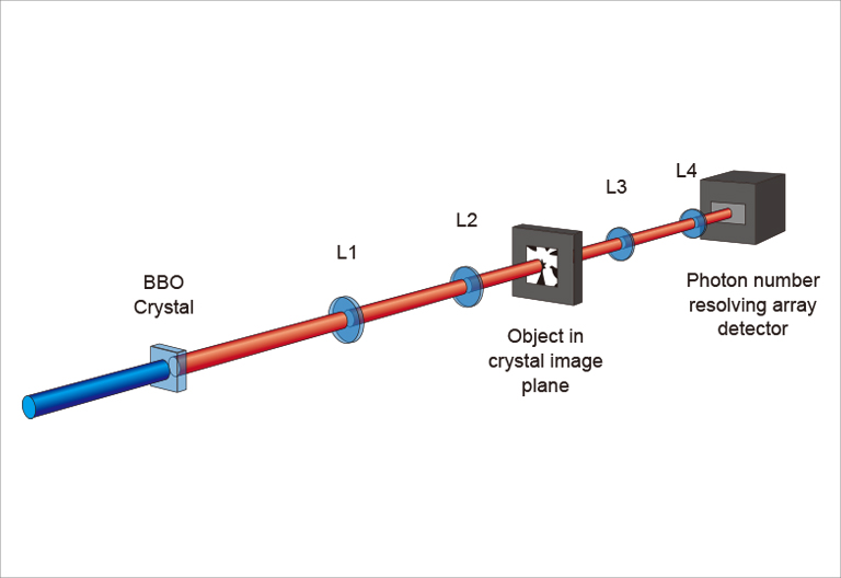
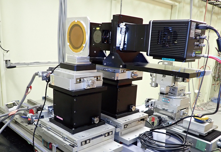
Experimental setup of Quantum imaging with ORCA-Quest
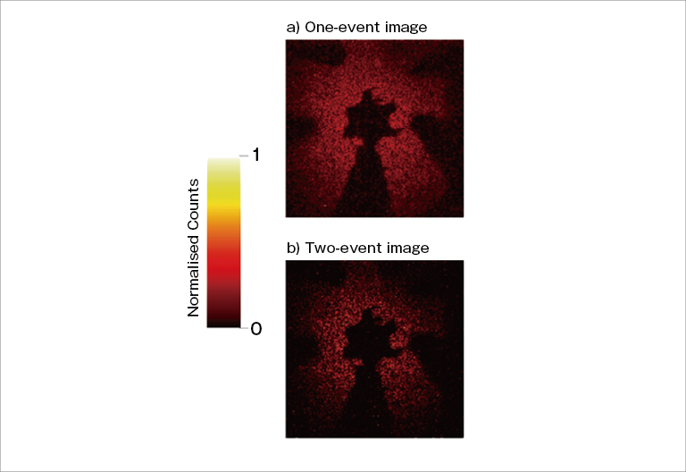
Images of Quantum imaging with ORCA-Quest
Data courtesy of Prof. Miles Padgett, University of Glasgow
Case study

Super-resolution microscopy
Super-resolution microscopy refers to a collection of methods to obtain a microscope image with a spatial resolution higher than the diffraction limit. Super-resolution microscopy needs scientific cameras with a combination of very low noise and small pixel size, resulting in a higher resolution.
Super-resolution images from ORCA-Quest
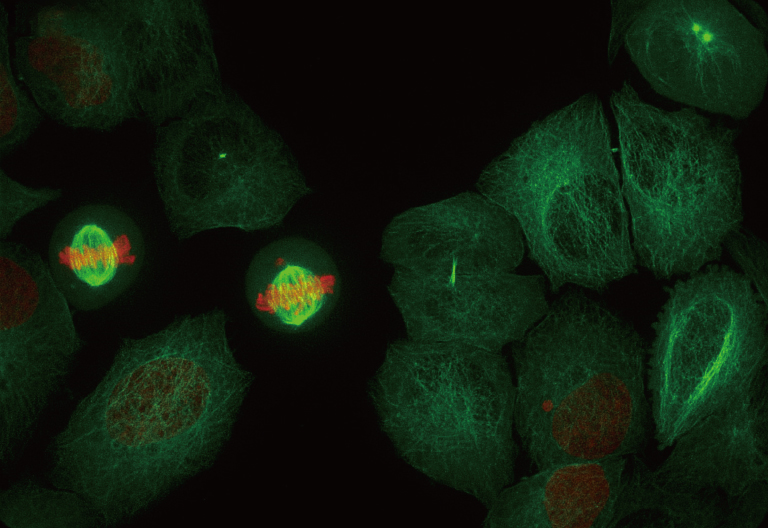
qCMOS camera / 4.6 μm pixel size
Super-resolution images from ORCA-Fusion
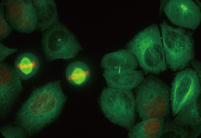
Gen III sCMOS camera / 6.5 μm pixel size
Experimental setup with ORCA-Quest
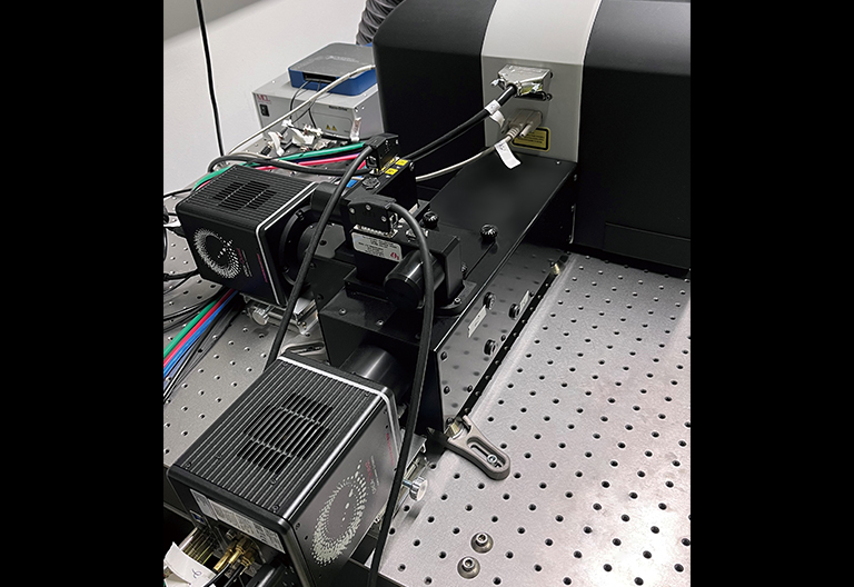
Data courtesy of Steven Coleman at VisiTech International with their VT-iSIM, high-speed super-resolution live cell imaging system.
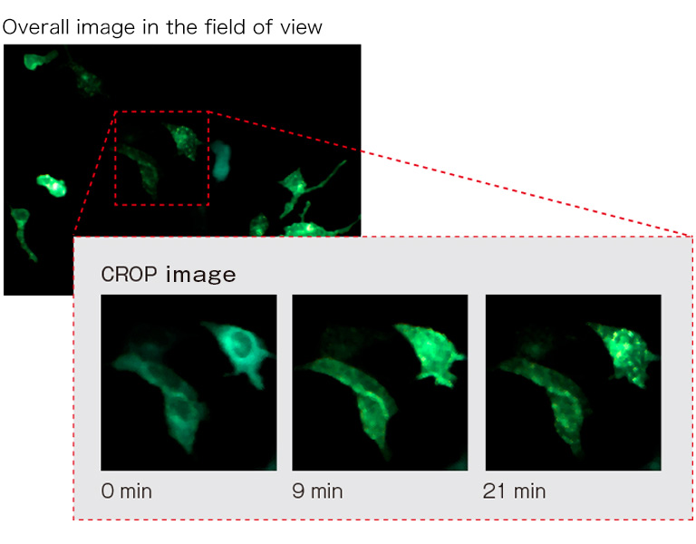
Bioluminescence
Bioluminescence microscopy has been gaining attention due to its unique advantages over conventional fluorescence microscopy, including the elimination of the need for excitation light. The major drawback of bioluminescence is its very low light intensity, resulting in long exposure times and low image quality. Bioluminescence research needs highly sensitive cameras, even with prolonged exposure.
Simultaneous dual wavelength luminescence imaging
NanoLuc fusion protein ARRB2 and Venus fusion protein V2R are nearby, and BRET is occurring.
Camera: ORCA-Quest + W-VIEW GEMINI
Objective: 20× / Exposure Time: 30 sec / Binning: 4×4
Appearance of the microscope system

Data courtesy of Dr. Masataka Yanagawa, Department of Molecular & Cellular Biochemistry Graduate School of Pharmaceutical Science, Tohoku University
Delayed fluorescence in plants
Plants release a tiny portion of the light energy they absorb for photosynthesis as light over a period of time. This phenomenon is known as delayed fluorescence. By detecting this faint light, it is possible to observe the effects of chemicals, pathogens, the environment, and other stressors on plants.
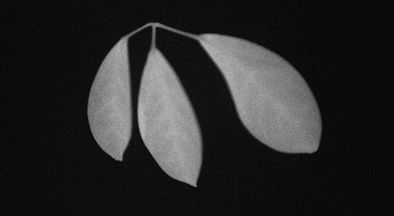
Delayed fluorescence of ornamental plants (exposure for 10 seconds after 10 seconds of excitation light quenching)
Case study

Lucky imaging
When observing stars from the ground, the image of the star can be blurred due to atmospheric turbulence, which substantially reduces the ability to capture clear images. However, with short exposures and the right atmospheric conditions, it is sometimes possible to capture clear images. For this reason, lucky imaging is a method of acquiring a large number of images and integrating only the clearest ones while aligning them.
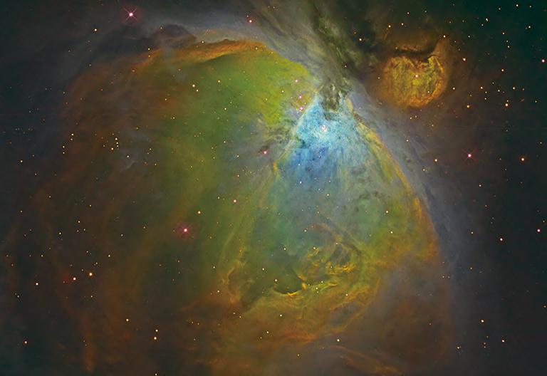
Orion Nebula (Color image with 3 wavelength filters)
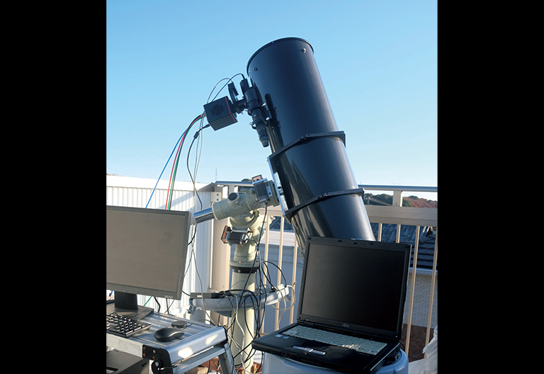
Imaging setup
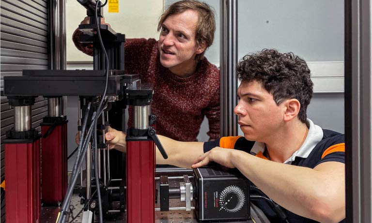
Adaptive optics
Adaptive optics is a method where systems immediately correct the wavefront of incoming light disturbed by atmospheric fluctuations. In order to perform real-time and highly accurate wavefront correction, a camera needs to take images with high speed and high spatial resolution. In addition, the camera also needs high sensitivity because the wavefront correction is performed in very dark conditions where a laser guide star is measured.
Wavefront correction by adaptive optics

Comparison of adaptive optics
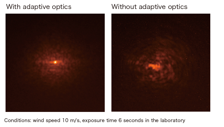
Data courtesy of Kodai Yamamoto, Ph.D., Department of Astronomy, Kyoto University
Case study

For imaging X-ray or other high-energy particles, a scientific camera coupled with a scintillator is often used. The imaging system must have low noise and high speed to detect momentary phenomena.
X-ray phase contrast CT image of mouse embryo
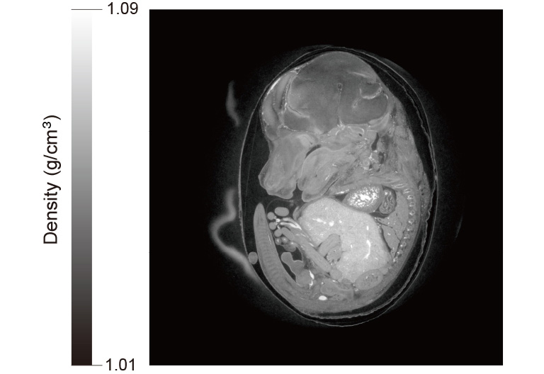
X-ray phase contrast CT image of a mouse embryo from an ORCA-Quest combined with high resolution X-ray imaging system (M11427)
Exposure time: 15 ms, Total measurement time: 6.5 min
Experimental setup
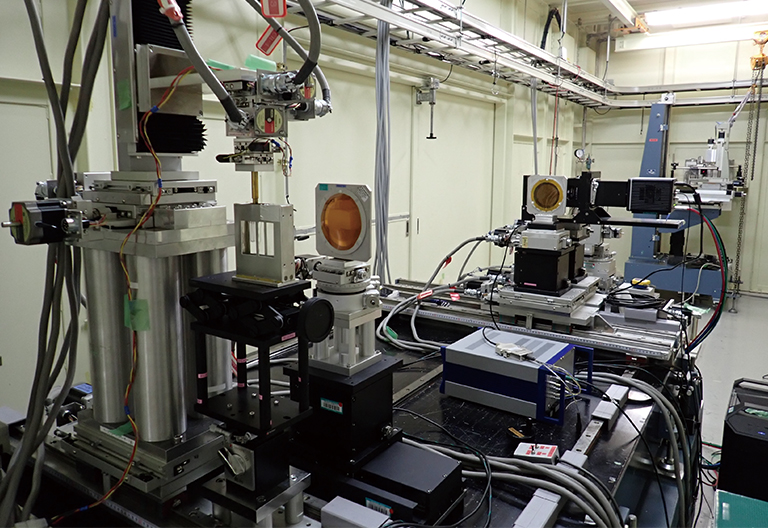
Camera setup
Data courtesy of SPring-8 BL20B2 beamline by Dr. Masato Hoshino, Senior scientist in Japan Synchrotron Radiation Research Institute (JASRI)
Case study

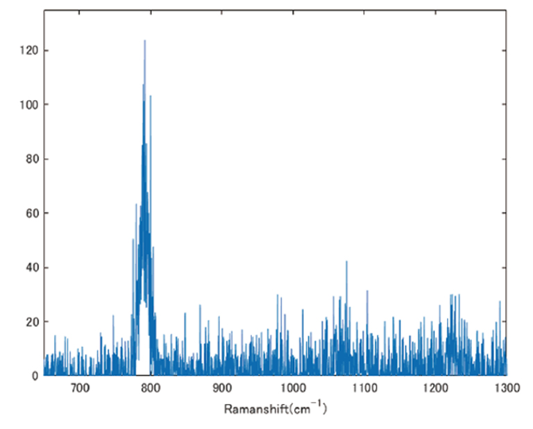
The Raman effect is the scattering of light at a wavelength different from that of the incident light. Raman spectroscopy is a technique for determining material properties by measuring this wavelength. This type of spectroscopy enables structural analysis at the molecular level, which provides information on aspects such as chemical bonding and crystallinity.
Raman spectrum (single frame) comparison under conditions of equal photon number per pixel in a line scan type Raman imaging system
Raman Image
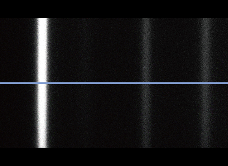
qCMOS camera
EM-CCD camera
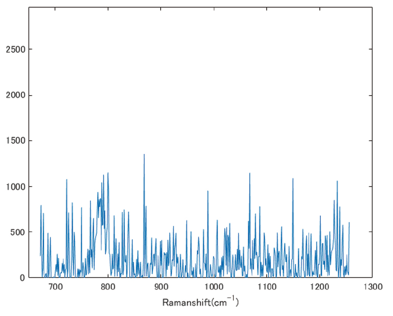
@10 photon/pixel/frame, 532 nm laser excitation
Reference: Photon number resolving capability of qCMOS camera for Raman spectroscopy and imaging
PC recommendation
With the introduction of the ORCA-Quest IQ, users are now able to stream 9.4 megapixel images to their computers 120 frames per second. The computer recommendations for this high data rate can be met by using the guidelines listed in the PC Recommendations for ORCA-Quest IQ.
Software

Our software provides the interface to access all our carefully engineered camera features, from simply setting exposure to orchestrating complex triggering for multidimensional experiments.
Specifications
| Product number | C15550-23UP |
|---|---|
| Imaging device | qCMOS image sensor |
| Effective number of pixels | 4096 (H) × 2304 (V) |
| Pixel size | 4.6 μm (H) × 4.6 μm (V) |
| Effective area | 18.841 mm (H) × 10.598 mm (V) |
| Quantum efficiency (typ.) | 85 % (peak QE) |
| Full well capacity (typ.) | 7000 electrons |
| Readout noise (typ.) | Standard scan: 0.43 electrons (rms), 0.39 electrons (median) Ultra quiet scan: 0.30 electrons (rms), 0.25 electrons (median) |
| Dynamic range (typ.) *1 | 23 000 : 1 (rms), 28 000 : 1 (median) |
| Dark signal non-uniformity (DSNU) (typ.) *2 | 0.06 electrons |
| Photoresponse non-uniformity (PRNU) (typ.) *2*3 | <0.1 % |
| Linearity error | 0.5 % |
| Cooling method (Peltier cooling) | Forced-air cooled (Ambient temperature: +25 °C): -10 ℃ Water cooled (Water temperature: +25 °C) *4: -10 ℃ Water cooled [max cooling (Water temperature: +20 ℃, Ambient temperature: +20 ℃)] *4: -25 ℃ (typ.) |
| Dark current (typ.) | Forced-air cooled (Ambient temperature: +25 °C): 0.032 electrons/pixels/s Water cooled (Water temperature: +25 °C) *4: 0.032 electrons/pixels/s Water cooled [max cooling (Water temperature: +20 ℃, Ambient temperature: +20 ℃)] *4: 0.012 electrons/pixels/s |
| Readout mode | Full resolution, Digital binning (2×2, 4×4), Sub-array |
| Frame rate at full resolution | Standard scan *5: 120 frames/s (CoaXPress), 28.7 frames/s (Full Configuration) *6, 7.19 frames/s (Base Configuration) *6 Ultra quiet scan: 25.4 frames/s (CoaXPress), 25.4 frames/s (Full Configuration) *6, 7.19 frames/s (Base Configuration) *6 |
| Exposure time | Standard scan *5: 7.2 μs to 1800 s Ultra quiet scan: 33.9 μs to 1800 s *7 |
| External trigger input mode | Edge / Global reset edge / Level / Global reset level / Sync readout / Start |
| Trigger delay function | 0 s to 10 s in 1 μs steps |
| Trigger output | Global exposure timing output / Any-row exposure timing output / Trigger ready output / 3 programmable timing outputs / High output / Low output |
| Master pulse | Pulse mode: Free running / Start trigger / Burst Pulse interval: 5 μs to 10 s in 1 μs step Burst count: 1 to 65 535 |
| Digital output | 16 bit, 12 bit, 8 bit |
| Image processing function | Defect pixel correction (ON or OFF, hot pixel correction 3 steps) |
| Interface | USB 3.1 Gen 1 *8, CoaXPress (Quad CXP-6) |
| Image output dedicated Interface *9 | Camera Link (SDR-26): Base Configuration / Full Configuration |
| Trigger input connector | SMA |
| Trigger output connector | SMA |
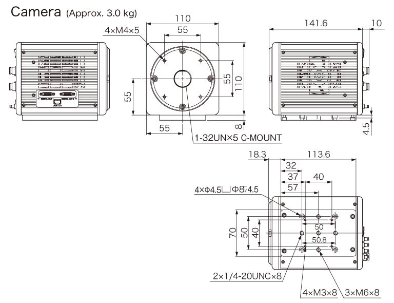
| Lens mount | C-mount |
| Power supply | AC100 V to AC240 V, 50 Hz/60 Hz |
| Power consumption | Approx. 155 VA |
| Ambient operating temperature | 0 °C to +35 °C |
| Ambient operating humidity | 30 % to 80 % (With no condensation) |
| Ambient storage temperature | -10 °C to +50 °C |
| Ambient storage humidity | 90 % Max. (With no condensation) |
*1: Calculated from the ratio of the full well capacity and the readout noise in Ultra quiet scan.
*2: In Ultra quiet scan.
*3: At 3500 electrons, the center 1500 × 1500 area of the image sensor, 1000 times integration.
*4: Water volume is 0.46 L/m.
*5: Normal area readout mode only.
*6: When using the USB interface, images are output from both the USB and Camera Link interfaces simultaneously, and the sensor's operating rate is limited by the speed of the Camera Link interface. At full resolution, if the sensor's operating rate exceeds 17.6 frames/s, the frame of the image acquired via the USB interface may be lost.
*7: For both global reset edge trigger and global reset level trigger, the minimum exposure time is 67.8 μs.
*8: Equivalent to USB 3.0 Gen 1.
*9: Images are output from the Camera Link I/F only when the camera is controlled via the USB I/F. Camera control via the Camera Link I/F is not possible.
Spectral response
Dimensions
We publish case study articles of our ORCAⓇ-Quest customers.
Related documents
Instruction manual
Technical note (For the previous model, ORCA-Quest)
Camera lineup catalog
Special sites
This site provides information on scientific cameras.
Since there is a wide range of camera types and performance, it is important to select the best camera for each application.
It introduces technical information, simulation tools, and examples of actual applications to help you fully understand the performance of the camera and select the best one for your application.
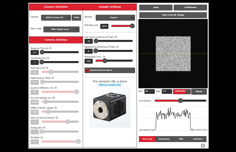
Camera simulation lab
When using a camera for industrial or research applications, it is necessary to select a camera based on various conditions such as the wavelength and light intensity of the image to be captured. We offer the "Camera simulation lab", a tool that allows users to intuitively compare the differences in imaging results due to camera performance while checking the simulated images.
Camera application case study collection
Synchrotron radiation analysis "Ryugu" camera application case study
Asteroid Ryugu, is believed to still contain water and organic compounds from approximately 4.6 billion years ago, when our solar system is thought to have formed. We interviewed Mr. Uesugi of the Japan Synchrotron Radiation Research Institute (JASRI), who was responsible for analyzing the Ryugu samples, regarding the methods and results of the analysis, and its future prospects.
This case study includes an interview with Mr. Uesugi and features our lineup of cameras suitable for synchrotron radiation imaging.

Astronomy camera application case study
Astronomy is a field where research is conducted to discover and explore unknown celestial bodies and astronomical phenomena. This brochure introduces examples of such applications and identifies which of our cameras are suitable for each application.

Related products
- Confirmation
-
It looks like you're in the . If this is not your location, please select the correct region or country below.
You're headed to Hamamatsu Photonics website for JP (English). If you want to view an other country's site, the optimized information will be provided by selecting options below.
In order to use this website comfortably, we use cookies. For cookie details please see our cookie policy.
- Cookie Policy
-
This website or its third-party tools use cookies, which are necessary to its functioning and required to achieve the purposes illustrated in this cookie policy. By closing the cookie warning banner, scrolling the page, clicking a link or continuing to browse otherwise, you agree to the use of cookies.
Hamamatsu uses cookies in order to enhance your experience on our website and ensure that our website functions.
You can visit this page at any time to learn more about cookies, get the most up to date information on how we use cookies and manage your cookie settings. We will not use cookies for any purpose other than the ones stated, but please note that we reserve the right to update our cookies.
1. What are cookies?
For modern websites to work according to visitor’s expectations, they need to collect certain basic information about visitors. To do this, a site will create small text files which are placed on visitor’s devices (computer or mobile) - these files are known as cookies when you access a website. Cookies are used in order to make websites function and work efficiently. Cookies are uniquely assigned to each visitor and can only be read by a web server in the domain that issued the cookie to the visitor. Cookies cannot be used to run programs or deliver viruses to a visitor’s device.
Cookies do various jobs which make the visitor’s experience of the internet much smoother and more interactive. For instance, cookies are used to remember the visitor’s preferences on sites they visit often, to remember language preference and to help navigate between pages more efficiently. Much, though not all, of the data collected is anonymous, though some of it is designed to detect browsing patterns and approximate geographical location to improve the visitor experience.
Certain type of cookies may require the data subject’s consent before storing them on the computer.
2. What are the different types of cookies?
This website uses two types of cookies:
- First party cookies. For our website, the first party cookies are controlled and maintained by Hamamatsu. No other parties have access to these cookies.
- Third party cookies. These cookies are implemented by organizations outside Hamamatsu. We do not have access to the data in these cookies, but we use these cookies to improve the overall website experience.
3. How do we use cookies?
This website uses cookies for following purposes:
- Certain cookies are necessary for our website to function. These are strictly necessary cookies and are required to enable website access, support navigation or provide relevant content. These cookies direct you to the correct region or country, and support security and ecommerce. Strictly necessary cookies also enforce your privacy preferences. Without these strictly necessary cookies, much of our website will not function.
- Analytics cookies are used to track website usage. This data enables us to improve our website usability, performance and website administration. In our analytics cookies, we do not store any personal identifying information.
- Functionality cookies. These are used to recognize you when you return to our website. This enables us to personalize our content for you, greet you by name and remember your preferences (for example, your choice of language or region).
- These cookies record your visit to our website, the pages you have visited and the links you have followed. We will use this information to make our website and the advertising displayed on it more relevant to your interests. We may also share this information with third parties for this purpose.
Cookies help us help you. Through the use of cookies, we learn what is important to our visitors and we develop and enhance website content and functionality to support your experience. Much of our website can be accessed if cookies are disabled, however certain website functions may not work. And, we believe your current and future visits will be enhanced if cookies are enabled.
4. Which cookies do we use?
There are two ways to manage cookie preferences.
- You can set your cookie preferences on your device or in your browser.
- You can set your cookie preferences at the website level.
If you don’t want to receive cookies, you can modify your browser so that it notifies you when cookies are sent to it or you can refuse cookies altogether. You can also delete cookies that have already been set.
If you wish to restrict or block web browser cookies which are set on your device then you can do this through your browser settings; the Help function within your browser should tell you how. Alternatively, you may wish to visit www.aboutcookies.org, which contains comprehensive information on how to do this on a wide variety of desktop browsers.
5. What are Internet tags and how do we use them with cookies?
Occasionally, we may use internet tags (also known as action tags, single-pixel GIFs, clear GIFs, invisible GIFs and 1-by-1 GIFs) at this site and may deploy these tags/cookies through a third-party advertising partner or a web analytical service partner which may be located and store the respective information (including your IP-address) in a foreign country. These tags/cookies are placed on both online advertisements that bring users to this site and on different pages of this site. We use this technology to measure the visitors' responses to our sites and the effectiveness of our advertising campaigns (including how many times a page is opened and which information is consulted) as well as to evaluate your use of this website. The third-party partner or the web analytical service partner may be able to collect data about visitors to our and other sites because of these internet tags/cookies, may compose reports regarding the website’s activity for us and may provide further services which are related to the use of the website and the internet. They may provide such information to other parties if there is a legal requirement that they do so, or if they hire the other parties to process information on their behalf.
If you would like more information about web tags and cookies associated with on-line advertising or to opt-out of third-party collection of this information, please visit the Network Advertising Initiative website http://www.networkadvertising.org.
6. Analytics and Advertisement Cookies
We use third-party cookies (such as Google Analytics) to track visitors on our website, to get reports about how visitors use the website and to inform, optimize and serve ads based on someone's past visits to our website.
You may opt-out of Google Analytics cookies by the websites provided by Google:
https://tools.google.com/dlpage/gaoptout?hl=en
As provided in this Privacy Policy (Article 5), you can learn more about opt-out cookies by the website provided by Network Advertising Initiative:
http://www.networkadvertising.org
We inform you that in such case you will not be able to wholly use all functions of our website.
Close