![]()
Products


We are actively taking measures to improve product quality levels.
Applications


Why Hamamatsu?
Support


Our company


Investors


Japan (EN)
Select your region or country.


The principle of confocal microscopy | MEMS confocal unit
The principle of confocal microscopy
Introduction to Confocal Microscopy Basics
Images obtained with a confocal microscope
Simply put, confocal microscopy is a microscopy technique that acquires images with out-of-focus light optically removed from the resulting image at the focal plane. The resulting images have less blur, higher contrast, and better resolution, which is the primary purpose of confocal uses. Since each image shows fluorescent samples in a specific focal plane, it is possible to construct three-dimensional images, by acquiring multiple images and sequentially changing z-axis focal plane positions. Such images can be used to accurately determine the three-dimensional positioning of the sample.
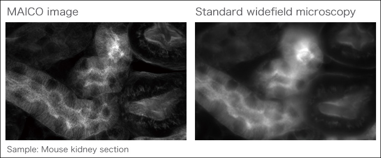
Figure 1: Comparison images between confocal microscopy and standard widefield microscopy.
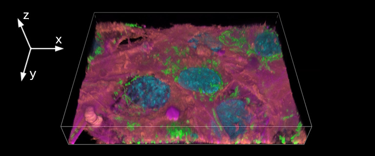
Figure 2: Example of a 3D image acquired with a confocal microscope.
From this point forward, the principles of confocal microscopy are explained in an easy-to-understand manner, showing how to remove light from outside the focal plane.
What is the difference between confocal and standard widefield microscopy?
Excitation light path and fluorescence emissions
In order to measure fluorescence, it is necessary to emit an excitation light to the samples. In this section, we will describe the principle of confocal microscopy by following the path of the excitation light including where it generates fluorescence.
In confocal microscopy, a laser beam, is used primarily as the excitation light source. Since the laser beam is a point light source with a good straight-line performance, its focus is on the focal plane through the objective lens forming a light spot.*1 In contrast to conventional widefield fluorescence microscopy, which excites the entire sample area at a time, confocal microscopy excites only one single point on the focal plane at a time.
*1: The combintion of objective lens magnification, NA, and excitation wavelength, determine the smallest spot size that can be focused. The higher the NA and the shorter the wavelength, the smaller the spot size and the higher the resolution.
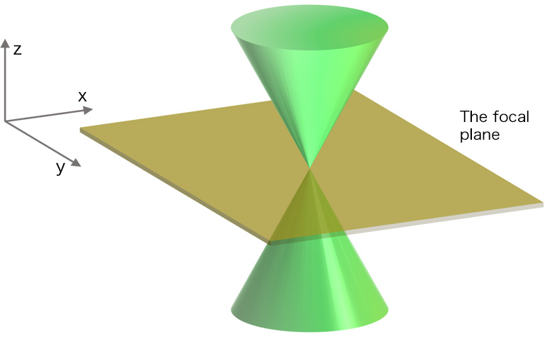
Figure 3: Conceptual diagram of the laser beam focus onto the focal plane.
Observing the light path travel through the air is challenging. For this reason, we placed a block of fluorescent material above the objective lens. As the excitation light from the objective lens passes through the block, the fluorescent material in the light path emits fluorescence in all directions. By observing the fluorescence, the path of the excitation light is traced as shown in Figure 4. The beam forms a spot at the focal plane, and on the other, when using conventional widefield microscopy, the excitation light remains spread out over the whole sample.
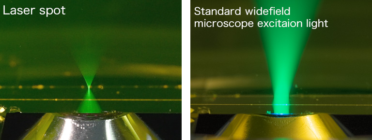
Figure 4: Comparison image between laser excitation light and standard widefield microscope excitation light.
As mentioned above, the laser beam is focused to a point on the focal plane forming a spot; however, in the z-direction, the laser beam is converged and diverged by the objective lens with a width corresponding to this process. As a matter of course, the laser light travels up and down the focal plane and when there is a fluorescent material, it emits fluorescence. In Figure 5, we can see that fluorescence is emitted above and below the focal plane in the fluorescent block.
This out-of-focus fluorescence also occurs in real samples and is the cause of blurred images. In confocal microscopy, the fluorescence emitted outside the focal plane is blocked from reaching the detector. This makes it possible to produce images using only the light from the focal plane.
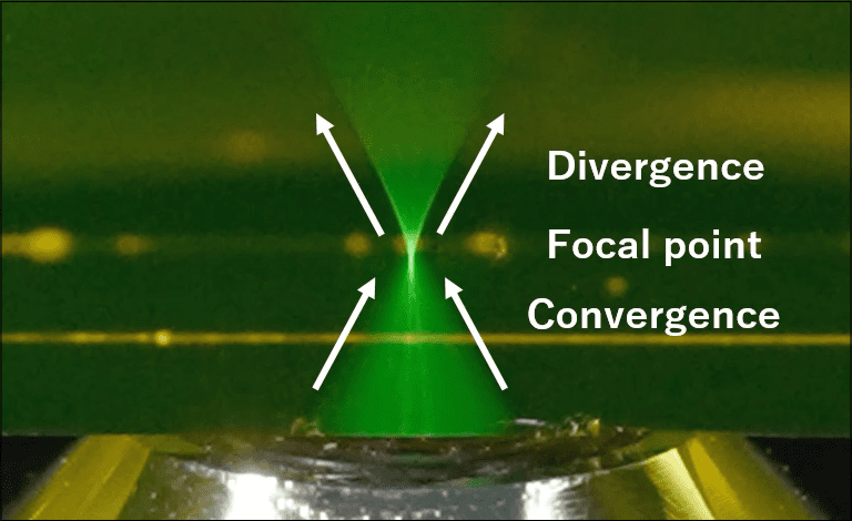
Figure 5: This figure shows how the laser beam converges and then diverges from the focal plane.
The key to confocal optics
Elimination of out-of-focus light by pinholes
How does confocal microscopy eliminate fluorescence outside the focal plane?
The principle of confocal microscopy may be explained by tracing the light path from the fluorescence generated at, above and below the focal plane directly to the detector.
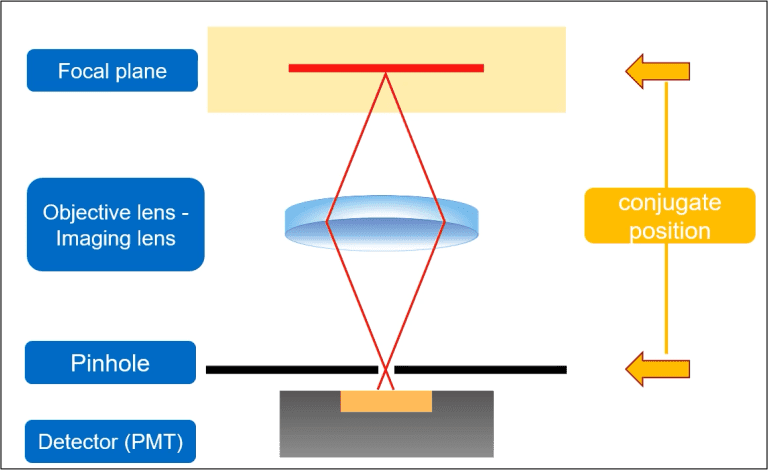
Figure 6: Conceptual diagram of the detection of fluorescence emitted from the focal plane.
The fluorescence generated at the objective focal plane passes from the objective lens through the imaging lens, and forms a focused image at the detector. A pinhole is placed at this position of the imaging system.
In this confocal optical scenario, the following three objects are usually placed at the conjugate points:
A. The light source (more precisely, the point source of light)
B. The focal plane of the objective lens
C. The pinhole in front of the detector
If points A, B and C are in a conjugate positional relationship, light emitted from any one of them will be focused on the other two points. When light emits from point A, it will focus on both point B and C. When light emits from point C, it will focus on both point A and B, and vice versa.
Therefore, in confocal optics, how does fluorescence emitted from the out of focus light source travel in the light path?
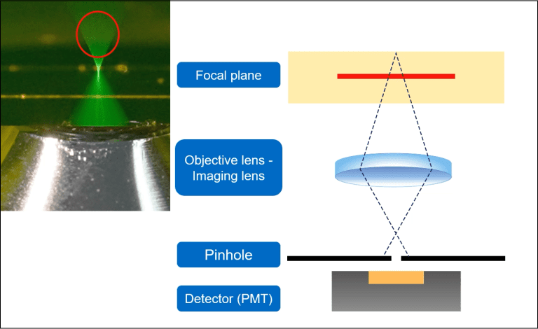
Figure 7: Conceptual diagram of the elimination technique of fluorescence emitted outside the focal plane.
Light emitted from the light source is focused at the objective lens focal plane and at the pinhole in front of the detector.
The newly generated fluorescence light at the focal plane of the objective lens is then focused at the pinhole in front of the detector. Excitation light emitted from the light source is rejected (blocked) by a bandpass filter, therefore it is not detected in a practical confocal system (in the blue circle on the left of Figure 7).
As shown in Figure 7, fluorescence emitted above the focal plane is focused above the pinhole and is largely blocked from reaching the detector because the light spreads out at the pinhole.
Secondly, fluorescence emitted at the bottom of the focal plane, as shown in the blue circle, is focused at the bottom of the pinhole and is therefore largely blocked from reaching the detector.*2
In this manner, only the fluorescence emitted from the focal plane can be directed to the detector.
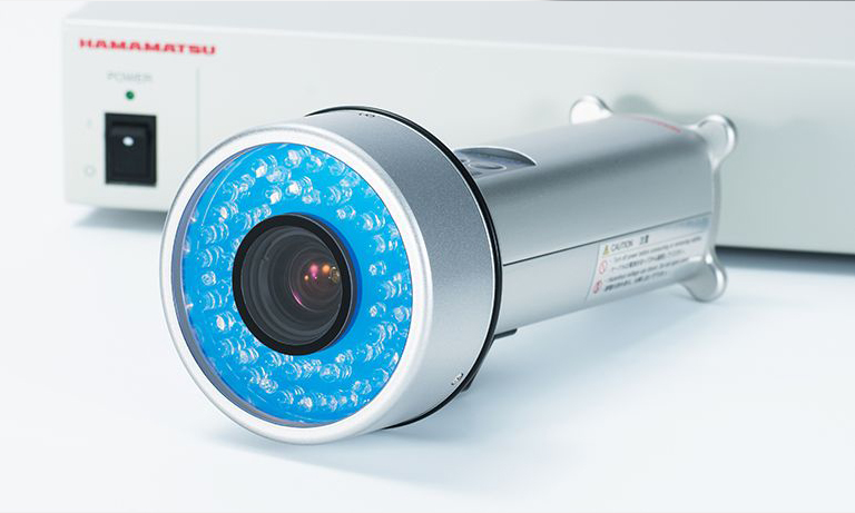
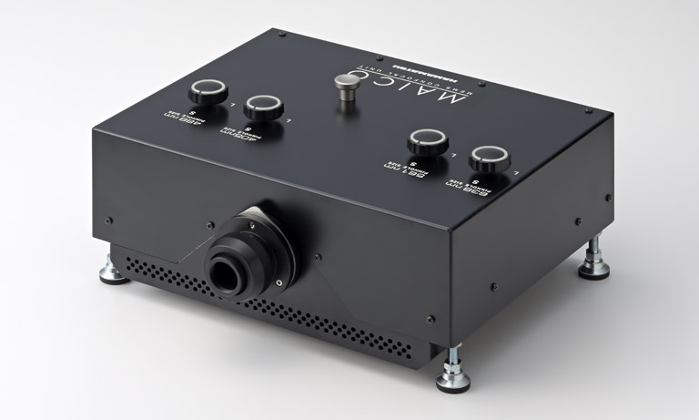
*2: As the light spot size on the sample varies with the objective lens, so does the fluorescence spot size at the pinhole position. In confocal microscopy, the pinhole size is usually adjusted to match the objective lens. In our confocal unit MAICOⓇ, three different pinhole sizes (S, M and L) can be selected according to the objective lens.
Excitation light will produce fluorescence anywhere in the light path if there is a fluorescent material present. However, by selecting only the fluorescence emitted from conjugate positions in the pinhole, it is possible to obtain an image originating only from the focal point. This is called optical slice image. The main advantage of confocal microscopy is the ability to obtain this optical slice from a thick sample.
Optical scanning to obtain two-dimensional images
The excitation light spot is fixed at a single point in the description so far, but in practice, the light spot is moved in a two-dimensional (x, y) direction with an optical scanning device to produce a single confocal fluorescence image. In our confocal unit MAICO, a MEMS mirror is used for this optical scanning.*3
Figure 8 shows the MEMS mirror changing its angle in the optical path and the associated lateral movement of the excitation spot on the sample. Figure 9 shows a schematic diagram of the successive optical scans of the sample plane.
*3 For more information on MEMS mirrors, please see the Features.
The scanning of the excitation spot has another advantage compared to widefield excitation. Adjacent fluorescent molecules are not excited, and are less likely to produce stray fluorescence.
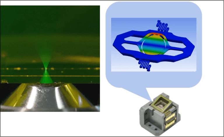
Figure 8*: Conceptual diagram of the movement of the MEMS mirror and the excitation light spot movement.
* This is different from the actual image acquisition operation.
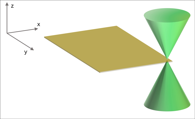
Figure 9: Conceptual diagram of planar scanning of the focal plane by the excitation light spot
PMT signal and image composition.
PMTs (photomultiplier tubes), which are photodetectors, output an electrical signal over time according to the amount of fluorescence incident on the light-receiving surface but do not have positional information.
On the other hand, an optical scanning device scans a fixed position in the XY direction for a fixed time.
The signal output by the PMT is reconstructed from the location of the signal at any given time. In other words, the temporal information of the signal intensity is transformed into spatial information, and the image is generated by assigning brightness information to the XY position of the image.
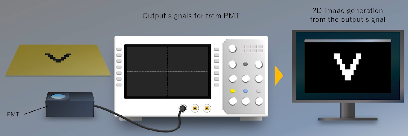
Figure 10: Example of conversion from PMT signal output over time to 2D image.
Measuring methods for three-dimensional images
As mentioned in the introduction, the optical section image obtained by confocal measurement reflects the specimen at a particular focal plane, so it is often possible to construct a three-dimensional image.
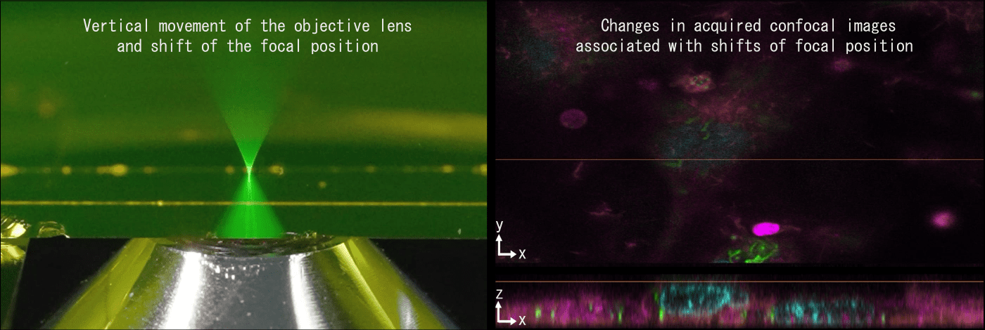
Figure 11*: The focused laser spot moves with the vertical movement of the objective lens and the acquired image changes accordingly.
Figure 11 shows that by moving the objective lens vertically, the focal position on the sample also moves vertically. As a result, the confocal image position also changes as the focal point moves vertically. The three-dimensional image in Figure 2 can be created by three-dimensionally reconstructing the individual confocal images derived from each height position acquired on the right side of Figure 11.
*In the image on the left of Figure 11, the light spot is not scanned, but in the actual measurement, it is scanned in the XY-plane by the scanning device. The focal point is moved up and down in successive steps.

MAICO enables imaging with reduced bleed-through between wavelengths, which is an issue in multi-wavelength simultaneous observation. We will introduce how we have achieved a reduction of bleed-through.


Discover case studies and interviews with customers who are using the MAICO MEMS confocal unit.

- Confirmation
-
It looks like you're in the . If this is not your location, please select the correct region or country below.
You're headed to Hamamatsu Photonics website for JP (English). If you want to view an other country's site, the optimized information will be provided by selecting options below.
In order to use this website comfortably, we use cookies. For cookie details please see our cookie policy.
- Cookie Policy
-
This website or its third-party tools use cookies, which are necessary to its functioning and required to achieve the purposes illustrated in this cookie policy. By closing the cookie warning banner, scrolling the page, clicking a link or continuing to browse otherwise, you agree to the use of cookies.
Hamamatsu uses cookies in order to enhance your experience on our website and ensure that our website functions.
You can visit this page at any time to learn more about cookies, get the most up to date information on how we use cookies and manage your cookie settings. We will not use cookies for any purpose other than the ones stated, but please note that we reserve the right to update our cookies.
1. What are cookies?
For modern websites to work according to visitor’s expectations, they need to collect certain basic information about visitors. To do this, a site will create small text files which are placed on visitor’s devices (computer or mobile) - these files are known as cookies when you access a website. Cookies are used in order to make websites function and work efficiently. Cookies are uniquely assigned to each visitor and can only be read by a web server in the domain that issued the cookie to the visitor. Cookies cannot be used to run programs or deliver viruses to a visitor’s device.
Cookies do various jobs which make the visitor’s experience of the internet much smoother and more interactive. For instance, cookies are used to remember the visitor’s preferences on sites they visit often, to remember language preference and to help navigate between pages more efficiently. Much, though not all, of the data collected is anonymous, though some of it is designed to detect browsing patterns and approximate geographical location to improve the visitor experience.
Certain type of cookies may require the data subject’s consent before storing them on the computer.
2. What are the different types of cookies?
This website uses two types of cookies:
- First party cookies. For our website, the first party cookies are controlled and maintained by Hamamatsu. No other parties have access to these cookies.
- Third party cookies. These cookies are implemented by organizations outside Hamamatsu. We do not have access to the data in these cookies, but we use these cookies to improve the overall website experience.
3. How do we use cookies?
This website uses cookies for following purposes:
- Certain cookies are necessary for our website to function. These are strictly necessary cookies and are required to enable website access, support navigation or provide relevant content. These cookies direct you to the correct region or country, and support security and ecommerce. Strictly necessary cookies also enforce your privacy preferences. Without these strictly necessary cookies, much of our website will not function.
- Analytics cookies are used to track website usage. This data enables us to improve our website usability, performance and website administration. In our analytics cookies, we do not store any personal identifying information.
- Functionality cookies. These are used to recognize you when you return to our website. This enables us to personalize our content for you, greet you by name and remember your preferences (for example, your choice of language or region).
- These cookies record your visit to our website, the pages you have visited and the links you have followed. We will use this information to make our website and the advertising displayed on it more relevant to your interests. We may also share this information with third parties for this purpose.
Cookies help us help you. Through the use of cookies, we learn what is important to our visitors and we develop and enhance website content and functionality to support your experience. Much of our website can be accessed if cookies are disabled, however certain website functions may not work. And, we believe your current and future visits will be enhanced if cookies are enabled.
4. Which cookies do we use?
There are two ways to manage cookie preferences.
- You can set your cookie preferences on your device or in your browser.
- You can set your cookie preferences at the website level.
If you don’t want to receive cookies, you can modify your browser so that it notifies you when cookies are sent to it or you can refuse cookies altogether. You can also delete cookies that have already been set.
If you wish to restrict or block web browser cookies which are set on your device then you can do this through your browser settings; the Help function within your browser should tell you how. Alternatively, you may wish to visit www.aboutcookies.org, which contains comprehensive information on how to do this on a wide variety of desktop browsers.
5. What are Internet tags and how do we use them with cookies?
Occasionally, we may use internet tags (also known as action tags, single-pixel GIFs, clear GIFs, invisible GIFs and 1-by-1 GIFs) at this site and may deploy these tags/cookies through a third-party advertising partner or a web analytical service partner which may be located and store the respective information (including your IP-address) in a foreign country. These tags/cookies are placed on both online advertisements that bring users to this site and on different pages of this site. We use this technology to measure the visitors' responses to our sites and the effectiveness of our advertising campaigns (including how many times a page is opened and which information is consulted) as well as to evaluate your use of this website. The third-party partner or the web analytical service partner may be able to collect data about visitors to our and other sites because of these internet tags/cookies, may compose reports regarding the website’s activity for us and may provide further services which are related to the use of the website and the internet. They may provide such information to other parties if there is a legal requirement that they do so, or if they hire the other parties to process information on their behalf.
If you would like more information about web tags and cookies associated with on-line advertising or to opt-out of third-party collection of this information, please visit the Network Advertising Initiative website http://www.networkadvertising.org.
6. Analytics and Advertisement Cookies
We use third-party cookies (such as Google Analytics) to track visitors on our website, to get reports about how visitors use the website and to inform, optimize and serve ads based on someone's past visits to our website.
You may opt-out of Google Analytics cookies by the websites provided by Google:
https://tools.google.com/dlpage/gaoptout?hl=en
As provided in this Privacy Policy (Article 5), you can learn more about opt-out cookies by the website provided by Network Advertising Initiative:
http://www.networkadvertising.org
We inform you that in such case you will not be able to wholly use all functions of our website.
Close