![]()
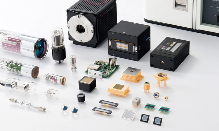
Products


We are actively taking measures to improve product quality levels.
Applications


Why Hamamatsu?
Resources


Support


Our company


Investors


United Kingdom (EN)
Select your region or country.
Distance image sensors and their applications
Distance image sensors are image sensors that measure the distance to the target object using the Indirect TOF (time-of-flight) method. Used in combination with a pulse modulated light source, these sensors output delay time signals according to the timing in which the light is emitted and received. The sensor signals are arithmetically processed by an external signal processing circuit or a PC to obtain distance data.
For distance imaging, we can also use a standard image sensor, however, it usually takes a microsecond to perform the charge transfer from the photosensitive area to the storage section. Hamamatsu’s distance image sensors can make the transfer in the order of tens of nanoseconds. Other key features of our distance image sensors are:
- Drive voltage 5V or less
- Reduced effect of background light
- Compact chip size package (CSP) type
Distance image sensors are the best solution for the measurement range of 20 m, with a distance resolution of a few centimeters, for other distances, sensors such as APD+TDC are recommended.
Figure 1: Indirect-TOF and Direct-TOF
comparison of distance resolution and measured distance.
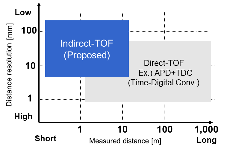
Measured distance and distance resolution depend on the design of the module. [Emitted Power, optical system (lens)]
Some example applications for distance image sensors are:
![]()
Obstacle detection
Self-driving, robot, etc.
![]()
Security
Surveillance camera, intrusion detection, etc.
![]()
Factory automation
Shape recognition, logistics, robots, object size, etc.
![]()
Motion capture, gesture
![]()
Touchless operation
Air conditioner, automatic door, etc.
Distance image sensor structure
Hamamatsu can provide linear and area distance image sensors. Compared to a typical CMOS image sensor, the distance image sensor features:
- Pixel structure that allows high-speed charge transfer.
- The voltage needed to calculate the distance is output from two terminals.
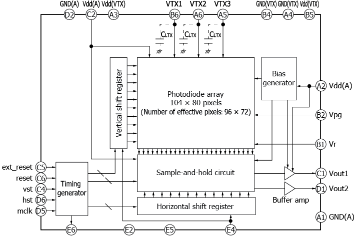
Figure 2: Block diagram of linear and area distance image sensors:
LINEAR
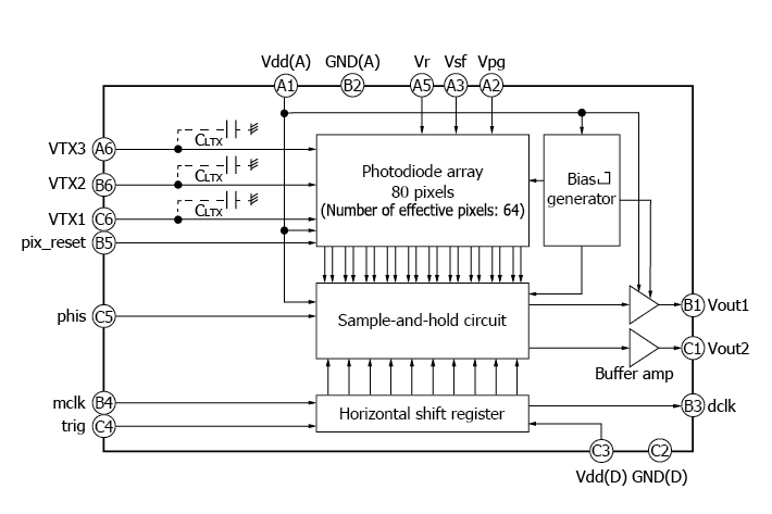
AREA
The distance image sensors have a pixel structure in which electrodes are formed on local oxidation of silicon (LOCOS), so they generate a fringe electric field like CCD image sensors.
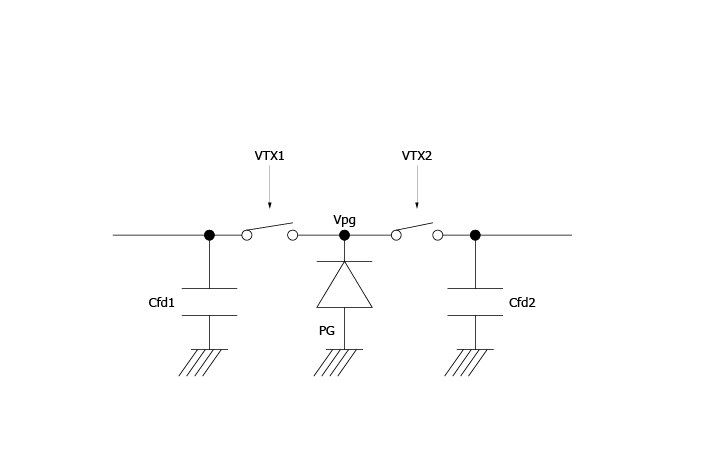
Figure 3: Pixel lateral surface potential
To obtain a high-speed charge transfer we use a pixel’s lateral surface potential to perform charge transfer and separation of the generated photoelectrons. In Figure 4 you can see the pixel structure.
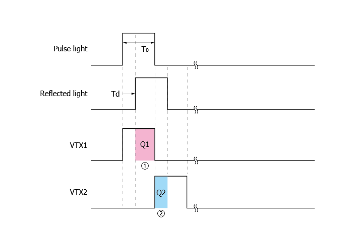
Figure 4: Pixel structure
In the first phase, the potential profile sloping down towards VFD1 results in electric fields that quickly transfer the generated photoelectrons during this phase from their generation site under this PG to VFD1 through gate VTx1. The same mechanism transfers photoelectrons to node VFD2 in phase 2.

The measurement range is calculated by each photoelectron (Q1 and Q2). As result we have realized high-speed charge transfer.
The number of electrons generated in each pulse emission is several e-. Therefore, the operation shown in Figure 4 is repeated several thousand to several tens of thousands of times, and then the accumulated charge is read out. The number of repetitions depends on the incident light level and the required accuracy of distance measurement.
Indirect ToF (Time-of-Flight)
As previously mentioned, distance image sensors are based on the Indirect ToF method. In general, the ToF method calculates the distance by calculating the length of time for a light pulse travel from the light source, be reflected off an object, and return to the sensor.
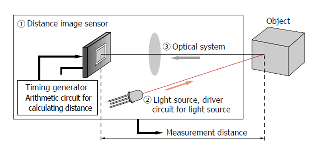
Figure 5: Configuration example direct ToF Method
Figure 5 describes the direct ToF method. When we consider the phase difference information of light emitted and received, we are using the Indirect ToF method. In this method the charge generated in the photosensitive area is transferred to the storage section synchronously with the pulse of the light source, and the distance is calculated from the integrated charge.
Figure 6: Basic principle indirect ToF Method
Pulses Vtx1 and Vtx2 are used to transfer generated electrons to two capacitance nodes (Vfd1 and Vfd2). From the accumulated charges in Q1 and Q2, and applying charge-to-voltage conversion, we obtain the output voltage Vout1 and Vout2:
Vout1 = Q1/Cfd1 = N x Iph x [(To-Td)/Cfd1]
Vout2 = Q2/Cfd2 = N x Iph x (Td/Cfd2)
Where:
Cfd1, Cfd2 are the integration capacitance of each output
N is the charge transfer clock count
Iph is the photocurrent
To is the pulse width of output light
Td is the delay time
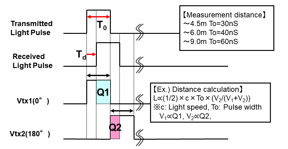
From the previous formula, when Cfd1 = Cfd2, we can easily obtain the delay time:
Td = [Vout2/(Vout1+Vout2)] x T0
And using the output values (Vout1, Vout2) according to the distance D, expressed by the formula:
D = ½ x c x Td = ½ x c x [Vout2(/(Vout1 + Vout2)] x T0
Background light elimination circuit
For all distance measurements, ambient light is a key factor. In the indirect ToF method we use the difference between the output voltages, so the distance can be measured when background light is present.
Figure 7: Signal charge and background light charge
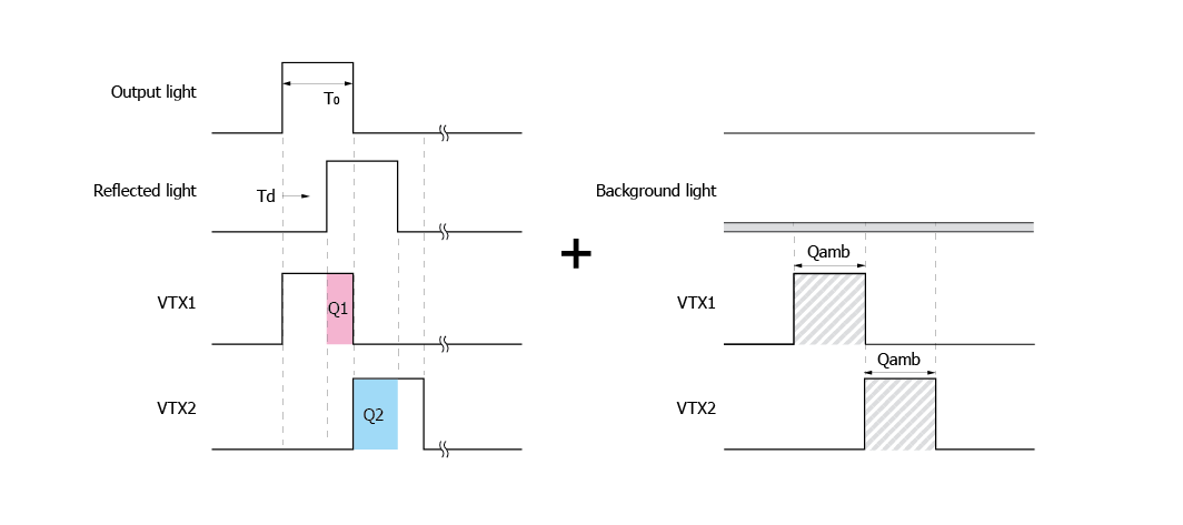
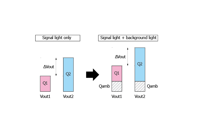
Figure 8: Integrated charge when background light is incident
However, if the charge generated by background is large it can impact the saturation of the integration capacitance and narrow the dynamic range. For this reason, our distance Image sensors are equipped with a background elimination circuit.
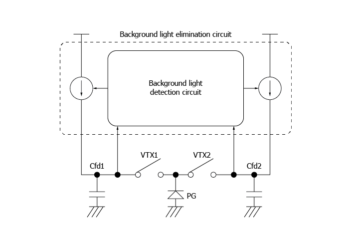
Figure 9: Background light elimination circuit
This background light detection circuit automatically operates when the output voltage approaches saturation. We denote the current caused by the signal light flowing through Cf1 and Cf2 as Iac1 and Iac2 and the current caused by background light as Iamb, but just to highlight the contribution of external light and to show how we can delete it. Remember that the chargescaused by Iac1, Iac2 and Iamb are not distinguished, and they are integrated simultaneously. For this reason we denote the current caused by the incident light (signal light + background light) flowing through Cfd1 and Cfd2 as Iph1 and Iph2.
Figure 10: Background elimination circuit off
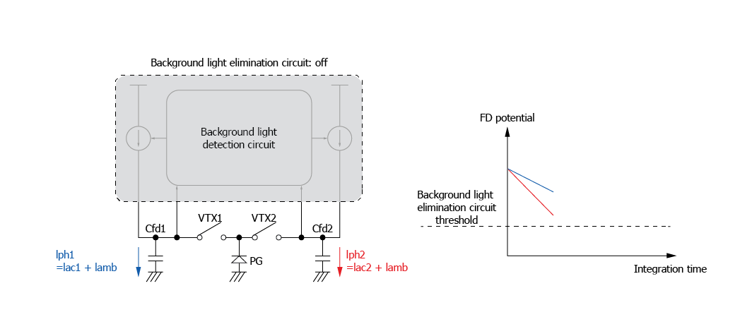
When the output voltage does not exceed the threshold, the circuit is off, and the background light is deleted from the ΔVout. From a numerical point of view we have:
Δvout1 = (Q1+Qamb)/Cfd1 = N x {[Iac1 x (T0-Td)]+(Iamb x T0 )}/Cfd1]
Δvout2 = (Q2+Qamb)/Cfd2 = N x {(Iac 2 x Td)]+(Iamb x T0 )}/Cfd2]
When the integration capacitance Cf1 and Cf2 are equal Δvout. Is:
Δvout= Δvout1 – Δvout2 = N x {[Iac1 x (T0 – Td)]- (Iac2 x Td)}/(Cf1 or Cf2)
As seen from the previous formula ΔVout is independent from Qamb (caused by the background light).
When one of the output voltages Vout1 or Vout2 exceed the threshold, the background circuit is activated and the larger of the two currents Iph1 and Iph2 is fed through Cfd1 and Cfd2. In the Figure 11 below, we will suppose that Iph1 is less than Iph2 so Iph2 is fed. In this situation the change in Vout2 is zero because the incoming current is equal to the outgoing current, and the electric potential is equal to the threshold of the background light elimination circuit. In the meantime, Cfd1 accumulates charge corresponding to Iph1-Iph2 and consequently Vout1 increases.
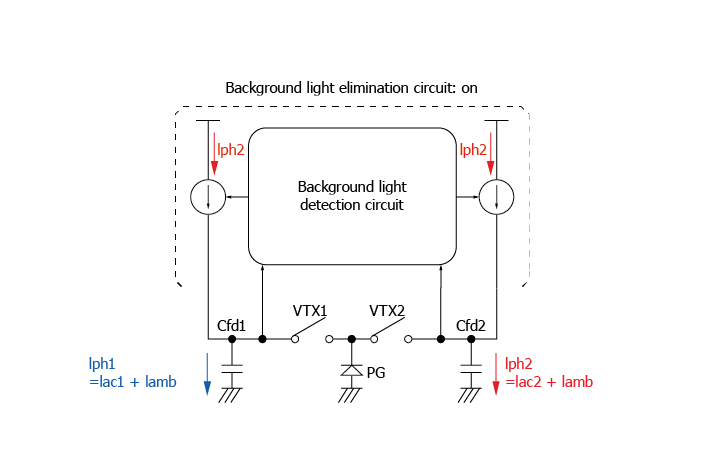
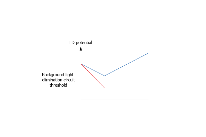
Figure 11: Background light elimination circuit: after operation (Iph1 <Iph2)
After the operation of the background light elimination circuit, we can describe ΔVout1 and ΔVout2 as:
ΔVout1 = [(Q1 + Qamb) – (Q2 + Qamb)]/Cf1 = (Q1-Q2)/Cf1=
= N x {[Iac1 x (T0-Td)+Iamb x T0]- [(Iac2 x Td) + (Iamb x T0)]}/Cf1=
N x {[Iac1 x (T0-Td)] - (Iac2 x Td) }/Cf1
ΔVout2 = [(Q2 + Qamb) – (Q2 + Qamb)]/Cfd2 = 0
When Cfd1 = Cfd2:
ΔVout= ΔVout1 - ΔVout2 = N x {[Iac1 x (T0 – Td)]- (Iac2 x Td)}/(Cf1 or Cf2)
Therefore, in this case, thanks to the operation of the background light elimination circuit, ΔVout is independent from Qamb (caused by the background light).
Additional features
Hamamatsu distance image sensors have many helpful features: detection of high-speed pulses, shutter operation, charge drain function.
We already see the classical structure of a photosensitive area with charge transfer gate VTX1 and VTX2, but our sensors have an additional gate, VTX3.
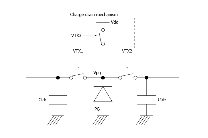
Figure 12: Structure of photosensitive area
When VTX1 and VTX2 are off and VTX3 is on, the charge drain function is active and thanks to this structure it is possible to drain unneeded charges caused by background light during the non-emission period.
This structure allows us to efficiently integrate a high-speed pulse light, or pulse laser diode sources, which can be used as a shutter.
Non-destructive readout
An additional interesting feature is the non-destructive readout method that allows the output of voltages at different integration times without resetting the capacitors Cfd1 and Cfd2 in the pixel.

Figure 13: Non-destructive readout
As showed in Figure 13, in each pixel of the CMOS image sensor the voltage output value during the accumulation can be read (multiple output). With this structure it is also possible to achieve low noise because the same frame difference of two data points cancels the reset noise generated when the pixel is reset. In addition, thanks to average processing, is possible to have high accuracy.
If we consider the impact of ambient light, we can have mainly two situations.
Figure 14: Non-destructive readout – advantages when applied to distance measurement system
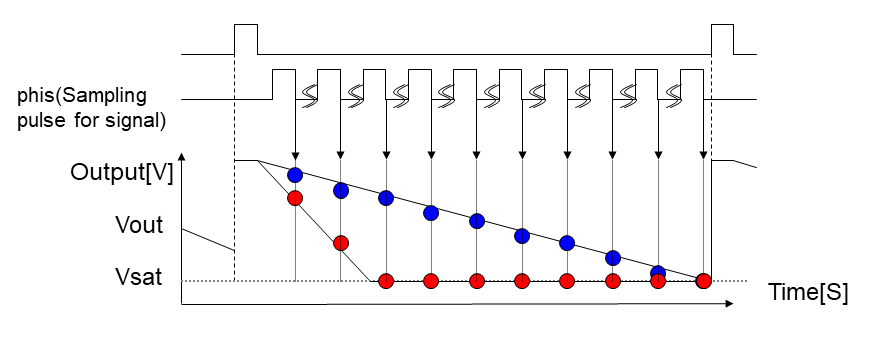
In Figure 14, the blue points are relative to weak ambient light. In this case we do not have saturation, so all the data can be used for the calculation. The red points represent a high level of ambient light. In this case we reach saturation and the data cannot be used, however using the limited initial data, we can calculate the slope and use an appropriate integration time.
One disadvantage of non-destructive readout is that the readout is performed several times in each frame, so the frame rate decreases as the number of readouts increase.
- Confirmation
-
It looks like you're in the . If this is not your location, please select the correct region or country below.
You're headed to Hamamatsu Photonics website for GB (English). If you want to view an other country's site, the optimized information will be provided by selecting options below.
In order to use this website comfortably, we use cookies. For cookie details please see our cookie policy.
- Cookie Policy
-
This website or its third-party tools use cookies, which are necessary to its functioning and required to achieve the purposes illustrated in this cookie policy. By closing the cookie warning banner, scrolling the page, clicking a link or continuing to browse otherwise, you agree to the use of cookies.
Hamamatsu uses cookies in order to enhance your experience on our website and ensure that our website functions.
You can visit this page at any time to learn more about cookies, get the most up to date information on how we use cookies and manage your cookie settings. We will not use cookies for any purpose other than the ones stated, but please note that we reserve the right to update our cookies.
1. What are cookies?
For modern websites to work according to visitor’s expectations, they need to collect certain basic information about visitors. To do this, a site will create small text files which are placed on visitor’s devices (computer or mobile) - these files are known as cookies when you access a website. Cookies are used in order to make websites function and work efficiently. Cookies are uniquely assigned to each visitor and can only be read by a web server in the domain that issued the cookie to the visitor. Cookies cannot be used to run programs or deliver viruses to a visitor’s device.
Cookies do various jobs which make the visitor’s experience of the internet much smoother and more interactive. For instance, cookies are used to remember the visitor’s preferences on sites they visit often, to remember language preference and to help navigate between pages more efficiently. Much, though not all, of the data collected is anonymous, though some of it is designed to detect browsing patterns and approximate geographical location to improve the visitor experience.
Certain type of cookies may require the data subject’s consent before storing them on the computer.
2. What are the different types of cookies?
This website uses two types of cookies:
- First party cookies. For our website, the first party cookies are controlled and maintained by Hamamatsu. No other parties have access to these cookies.
- Third party cookies. These cookies are implemented by organizations outside Hamamatsu. We do not have access to the data in these cookies, but we use these cookies to improve the overall website experience.
3. How do we use cookies?
This website uses cookies for following purposes:
- Certain cookies are necessary for our website to function. These are strictly necessary cookies and are required to enable website access, support navigation or provide relevant content. These cookies direct you to the correct region or country, and support security and ecommerce. Strictly necessary cookies also enforce your privacy preferences. Without these strictly necessary cookies, much of our website will not function.
- Analytics cookies are used to track website usage. This data enables us to improve our website usability, performance and website administration. In our analytics cookies, we do not store any personal identifying information.
- Functionality cookies. These are used to recognize you when you return to our website. This enables us to personalize our content for you, greet you by name and remember your preferences (for example, your choice of language or region).
- These cookies record your visit to our website, the pages you have visited and the links you have followed. We will use this information to make our website and the advertising displayed on it more relevant to your interests. We may also share this information with third parties for this purpose.
Cookies help us help you. Through the use of cookies, we learn what is important to our visitors and we develop and enhance website content and functionality to support your experience. Much of our website can be accessed if cookies are disabled, however certain website functions may not work. And, we believe your current and future visits will be enhanced if cookies are enabled.
4. Which cookies do we use?
There are two ways to manage cookie preferences.
- You can set your cookie preferences on your device or in your browser.
- You can set your cookie preferences at the website level.
If you don’t want to receive cookies, you can modify your browser so that it notifies you when cookies are sent to it or you can refuse cookies altogether. You can also delete cookies that have already been set.
If you wish to restrict or block web browser cookies which are set on your device then you can do this through your browser settings; the Help function within your browser should tell you how. Alternatively, you may wish to visit www.aboutcookies.org, which contains comprehensive information on how to do this on a wide variety of desktop browsers.
5. What are Internet tags and how do we use them with cookies?
Occasionally, we may use internet tags (also known as action tags, single-pixel GIFs, clear GIFs, invisible GIFs and 1-by-1 GIFs) at this site and may deploy these tags/cookies through a third-party advertising partner or a web analytical service partner which may be located and store the respective information (including your IP-address) in a foreign country. These tags/cookies are placed on both online advertisements that bring users to this site and on different pages of this site. We use this technology to measure the visitors' responses to our sites and the effectiveness of our advertising campaigns (including how many times a page is opened and which information is consulted) as well as to evaluate your use of this website. The third-party partner or the web analytical service partner may be able to collect data about visitors to our and other sites because of these internet tags/cookies, may compose reports regarding the website’s activity for us and may provide further services which are related to the use of the website and the internet. They may provide such information to other parties if there is a legal requirement that they do so, or if they hire the other parties to process information on their behalf.
If you would like more information about web tags and cookies associated with on-line advertising or to opt-out of third-party collection of this information, please visit the Network Advertising Initiative website http://www.networkadvertising.org.
6. Analytics and Advertisement Cookies
We use third-party cookies (such as Google Analytics) to track visitors on our website, to get reports about how visitors use the website and to inform, optimize and serve ads based on someone's past visits to our website.
You may opt-out of Google Analytics cookies by the websites provided by Google:
https://tools.google.com/dlpage/gaoptout?hl=en
As provided in this Privacy Policy (Article 5), you can learn more about opt-out cookies by the website provided by Network Advertising Initiative:
http://www.networkadvertising.org
We inform you that in such case you will not be able to wholly use all functions of our website.
Close