![]()
Products


We are actively taking measures to improve product quality levels.
Applications


Why Hamamatsu?
Resources


Support


Our company


Investors


United Kingdom (EN)
Select your region or country.
FAQs | UVTRON®: Flame / Discharge sensors
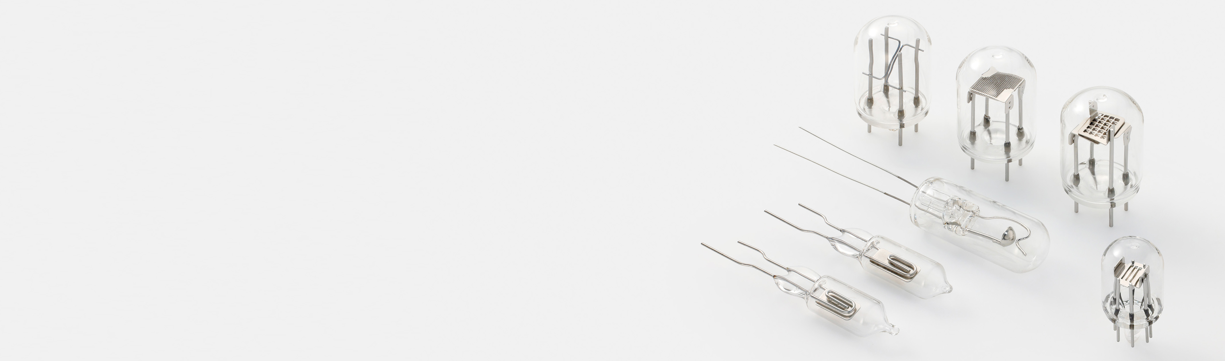
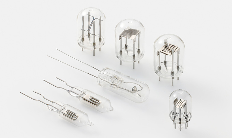
UVTRON® is a sensor sensitive only to UV light with wavelengths of 185 nm to 260 nm (*1).
Featuring high sensitivity and quick response, UVTRON® is ideal for detecting flame and electrical discharge.
*1: For nickel (Ni) electrodes
- What features does UVTRON® have compared to other sensors ?
- Which model of UVTRON® should I choose ?
- Can the sensor also detect cigarettes and incense sticks ?
- Can the sensor distinguish the size of a flame ?
- Is it possible to use multiple UVTRON® sensors at the same time ?
- What items are needed to operate the sensor ?
- What is the best way to measure the supply voltage for UVTRON® ?
- What daily inspection should be performed ?
- How long can UVTRON® be stored ?
Also, what is the best way to check the operation of UVTRON® after it has been stored for a long time ? - What happens if the supply voltage is changed ?
- What is defined as the end of life for the sensor ?
- What is the best way to bend the lead wires on UVTRON® ? Also, what is the best method to cut them ?
- What are the precautions when soldering the sensor ?
Is it OK to use a solder bath ? - Should I be careful of the orientation and position when installing UVTRON® ?
- When there are multiple anode leads and cathode leads, do all of them have to be connected ?
- Is it OK to set up UVTRON® far away from the driver circuit ?
- What causes background noise (BG) ?
- How can I prevent background noise (BG) ?
Also, how do I change the cancellation level ? - What is the intensity of light of the checker lamp ?
- Is it OK to use the sensor in high temperature, low temperature, and high humidity environments ?
- Why will just dropping the sensor cause it to become defective ?
- Can the sensor still be used when dirty ?
- Does the sensor comply with each type of certification, directive and regulation ?
- I would like to trial use the sensor. Who should I contact ?
光源設置環境について
What features does UVTRON® have compared to other sensors ?
UVTRON® is a sensor sensitive only to UV light with wavelengths of 185 nm to 260 nm (*1).
It can detect UV light with high sensitivity and has a quick response when compared with infrared light systems and smoke detection systems.
*1: For nickel (Ni) electrodes
Which model of UVTRON® should I choose ?
Select the best UVTRON® model based on the required sensitivity and the conditions where it will be used.
Please refer to the characteristics and specifications.
Can the sensor also detect cigarettes and incense sticks ?
The sensor is sensitive to UV light from flame so cannot detect flameless combustion such as cigarettes and incense sticks.
Can the sensor distinguish the size of a flame ?
Due to the characteristics of UVTRON®, it is slightly linear in application. Therefore, it is recommended to use it as an ON-OFF sensor to detect the presence of UV light, not as a sensor to measure the intensity of light.
Is it possible to use multiple UVTRON® sensors at the same time ?
Yes, it is possible.
However, when a UVTRON® sensor detects UV light, it discharges and emits UV light. Therefore, a neighboring UVTRON® sensor may detect the UV light emitted from the first sensor. Design the multiple sensor setup so that each UVTRON® sensor does not cause optical interference with neighboring sensors.
What items are needed to operate the sensor ?
One of the following items are required to operate UVTRON®.
1. An external CR quenching circuit and a DC high-voltage source
2. A DC-DC converter type high-voltage power supply circuit
At Hamamatsu Photonics, we offer UVTRON® driver circuits C10807 and C10423 that use a DC-DC converter type high-voltage power supply circuit. Please contact us if you would like more information about this product.
Circuit configuration
for an external CR quenching circuit and a DC high-voltage source

Circuit configuration
for a DC-DC converter type high-voltage power supply circuit

What is the best way to measure the supply voltage for UVTRON® ?
Use a high impedance multimeter of approximately 10 GΩ to measure the supply voltage for UVTRON®. If the multimeter does not have enough impedance, it may not be possible to measure the voltage accurately due to the high impedance of the UVTRON® driver circuit.
Circuit configuration
for voltage measurement circuit with high resistance

What daily inspection should be performed ?
Check whether UVTRON® detects UV light based on the ON-OFF operation of the checker lamp L9657-03. When doing so, be careful to ensure that UV light from an external source does not enter the UVTRON® sensor.
How long can UVTRON® be stored ?
Also, what is the best way to check the operation of UVTRON® after it has been stored for a long time ?
The warranty period is one year from the date of delivery, and the sensor can usually be stored for approximately five years.
After storing for a long time, check if there is any deterioration of the sensor, such as rust on the lead pins, before checking operation. It depends on how the sensor was stored, but generally, if there is no deterioration such as rust, then there should be no problems with operating the sensor.
What happens if the supply voltage is changed ?
If the supply voltage is increased, sensitivity will increase in proportion to the voltage increase. However, when the supply voltage exceeds the recommended operating range, background noise (BG) increases so it is recommended to use the sensor within the recommended supply voltage range.
Sensitivity characteristics
in relation to the supply voltage
(Typ.)

Background noise characteristics
in relation to the supply voltage
(Typ.)

VL: Discharge starting voltage under UV light
VD: Dielectric breakdown voltage between electrodes under fluorescent light
What is defined as the end of life for the sensor ?
The sensor has reached the end of life when any of the following situations occur.
1. When the discharge starting voltage reaches the maximum value in the specifications
2. When sensitivity falls to 50 % of the initial value
3. When background noise reaches the maximum value in the specifications
What is the best way to bend the lead wires on UVTRON® ? Also, what is the best method to cut them ?
The lead wires can be bent and cut on three sensor types, which are R2868, R9454 and R244. Lead wires on any of the other sensor types must not be processed (cut or bent).
How to bend lead wires
Carefully bend the lead wires after firmly securing them in place to ensure the glass bulb does not break or become scratched.
Good example

Bad example

How to cut lead wires
When processing the lead wires by cutting them, the internal electrodes may be subject to shocks. This may degrade the electrical characteristics to the same extent as if the sensor were dropped. To mitigate these shocks on the internal electrodes, cut the lead wires with the cutting edges of the nippers set perpendicular to the internal electrodes. The lead wires should be cut slowly two or three times using the nippers instead of cutting through the lead wires all at once.
Good example

Bad example

What are the precautions when soldering the sensor ?
Is it OK to use a solder bath ?
Applying excessive heat to the UVTRON® lead wires during soldering may cause the glass bulb to crack or the internal electrodes to deteriorate. This will lead to faulty operation, so be extra careful when soldering. For the sensors with hard pin lead wires, it is recommended to use one of the dedicated sockets that we provide. When soldering a sensor directly onto a printed circuit board, use heatsink tweezers or a similar tool to grip the root of the lead wires to prevent heat from conducting to the UVTRON® sensor, and then solder at a temperature of 350 °C or less within 5 seconds. Avoid using a solder bath. When finished soldering, be sure to completely wipe away the soldering flux with alcohol, etc.
Should I be careful of the orientation and position when installing UVTRON® ?
In terms of the orientation when installing the sensor, view characteristics are listed in the product information section. Refer to this information when installing the sensor to ensure that UV light can directly enter the cathode (photocathode).
There are no restrictions concerning the position when installing the sensor.

When there are multiple anode leads and cathode leads, do all of them have to be connected ?
As long as one of each of the anode leads and cathode leads are connected, the sensor will operate without any problems.
Is it OK to set up UVTRON® far away from the driver circuit ?
If UVTRON® must be installed far away from the driver circuit and the cable capacitance exceeds 100 pF, insert a current limiting resistor (RS: 4.7 kΩ) immediately before (within 25 mm) the UVTRON® anode.
If the cable has a high stray capacitance, the discharge current will also be high, which may damage the electrodes.
Circuit configuration for an external CR quenching circuit
・When installing UVTRON® far away

What causes background noise (BG) ?
Cause of background noise (BG) include the following:
1. Radiation including cosmic rays
When radiation with higher energy than UV light is incident on the cathode (photocathode), a discharge can be caused due to the photoelectric effect. As it is difficult to completely prevent the entry of radiation such as cosmic rays, which exist in nature, it is necessary to use a signal processing circuit to distinguish it from UV light from a detection target.
2. X-rays
When X-rays with higher energy and penetrating properties than UV light is incident on the cathode (photocathode), a discharge can be caused due to the photoelectric effect.
3. Static electricity
When an object charged with static electricity comes close to or makes contact with UVTRON®, the high electric field may ionize the gas molecules in the tube and cause a discharge.
4. High electric fields, high magnetic fields, and strong electromagnetic waves
Under high supply voltage conditions, the electric field emission from the cathode (photocathode) may cause photoelectrons to jump out, and this may trigger a discharge.
5. Intense light (such as from lasers and LEDs) with extremely high radiant intensity greater than sunlight
When intense light with extremely high radiant intensity is incident on the cathode (photocathode), background noise can increase due to thermionic emission and other factors.
6. Unintentional UV light
While this is normal for UVTRON® operation, UV light from sources other than a detection target may cause the device to malfunction. This also can be considered as a type of background noise (BG). UV light is also found abundantly in ordinary life. Especially outdoors, UVTRON® reacts to faint UV light from unexpected sources, such as sparks from arc welding or electrical sparks (sparks from a train pantograph). Take sufficient precautions for the area where UVTRON® is installed and used.
How can I prevent background noise (BG) ?
Also, how do I change the cancellation level ?
Be careful to ensure that unintended UV light does not enter the sensor. However, since it is not possible to avoid UVTRON® from reacting to the effects of cosmic rays, it is recommended to use a signal processing circuit that cancels background noise (BG). Our UVTRON® driver circuit C10807 and C10423 are equipped with background noise (BG) cancelling functions. Please contact us if you would like to change the cancellation level.
Signal processing circuit configuration

What is the intensity of light of the checker lamp ?
The lamp emits UV light that is similar in intensity to a lighter.
The lamp is considered to be harmless according to IEC62471 “Photobiological safety of lamps and lamp systems.” However, avoid directly looking into the lamp with the naked eye for long periods of time.
Is it OK to use the sensor in high temperature, low temperature, and high humidity environments ?
Be sure to keep to the specified operating temperature range of -40 ℃ to +125 ℃ and operating humidity range of 80 % or less when using UVTRON®.
The following tends to occur when using the sensor in high temperature, low temperature, and high humidity environments.
● Under high temperature, the sensor deteriorates faster.
● Under low temperature, the discharge starting voltage under UV light (VL) drops and sensitivity increases.
● Under high humidity, operation becomes unstable due to voltage leaks and short circuiting.
If operating humidity exceeds 80 %, ensure that no moisture forms on the sensor. Also, be careful to ensure there is sufficient insulation around the lead wires, such as covering the lead wires with insulating resin.
Why will just dropping the sensor cause it to become defective ?
Because excessive shock on UVTRON® may cause the anode and cathode to come into contact with each other, which can significantly shorten its lifespan.
Can the sensor still be used when dirty ?
If the glass bulb is dirty, UV light transmittance will drop and this may cause the glass to deteriorate. After installing the sensor onto equipment, periodically wipe the glass bulb with gauze or cleaning wipes moistened with alcohol to keep it clean. When handling UVTRON®, do not touch the glass bulb with your bare hands. Wear gloves to prevent oil and grime from your hands sticking to the glass bulb.
Does the sensor comply with each type of certification, directive and regulation ?
The UVTRON® sensor, socket, and checker lamp are not covered by CE certification. However, the UVTRON® driver circuit, checker lamp driver circuit, and module comply with CE certification.
All of these products comply with the RoHS directive.
Please contact us for information about the REACH regulation.
I would like to trial use the sensor. Who should I contact ?
We provide free demo units on loan for trial use. Please contact us for more information any time.
- Confirmation
-
It looks like you're in the . If this is not your location, please select the correct region or country below.
You're headed to Hamamatsu Photonics website for GB (English). If you want to view an other country's site, the optimized information will be provided by selecting options below.
In order to use this website comfortably, we use cookies. For cookie details please see our cookie policy.
- Cookie Policy
-
This website or its third-party tools use cookies, which are necessary to its functioning and required to achieve the purposes illustrated in this cookie policy. By closing the cookie warning banner, scrolling the page, clicking a link or continuing to browse otherwise, you agree to the use of cookies.
Hamamatsu uses cookies in order to enhance your experience on our website and ensure that our website functions.
You can visit this page at any time to learn more about cookies, get the most up to date information on how we use cookies and manage your cookie settings. We will not use cookies for any purpose other than the ones stated, but please note that we reserve the right to update our cookies.
1. What are cookies?
For modern websites to work according to visitor’s expectations, they need to collect certain basic information about visitors. To do this, a site will create small text files which are placed on visitor’s devices (computer or mobile) - these files are known as cookies when you access a website. Cookies are used in order to make websites function and work efficiently. Cookies are uniquely assigned to each visitor and can only be read by a web server in the domain that issued the cookie to the visitor. Cookies cannot be used to run programs or deliver viruses to a visitor’s device.
Cookies do various jobs which make the visitor’s experience of the internet much smoother and more interactive. For instance, cookies are used to remember the visitor’s preferences on sites they visit often, to remember language preference and to help navigate between pages more efficiently. Much, though not all, of the data collected is anonymous, though some of it is designed to detect browsing patterns and approximate geographical location to improve the visitor experience.
Certain type of cookies may require the data subject’s consent before storing them on the computer.
2. What are the different types of cookies?
This website uses two types of cookies:
- First party cookies. For our website, the first party cookies are controlled and maintained by Hamamatsu. No other parties have access to these cookies.
- Third party cookies. These cookies are implemented by organizations outside Hamamatsu. We do not have access to the data in these cookies, but we use these cookies to improve the overall website experience.
3. How do we use cookies?
This website uses cookies for following purposes:
- Certain cookies are necessary for our website to function. These are strictly necessary cookies and are required to enable website access, support navigation or provide relevant content. These cookies direct you to the correct region or country, and support security and ecommerce. Strictly necessary cookies also enforce your privacy preferences. Without these strictly necessary cookies, much of our website will not function.
- Analytics cookies are used to track website usage. This data enables us to improve our website usability, performance and website administration. In our analytics cookies, we do not store any personal identifying information.
- Functionality cookies. These are used to recognize you when you return to our website. This enables us to personalize our content for you, greet you by name and remember your preferences (for example, your choice of language or region).
- These cookies record your visit to our website, the pages you have visited and the links you have followed. We will use this information to make our website and the advertising displayed on it more relevant to your interests. We may also share this information with third parties for this purpose.
Cookies help us help you. Through the use of cookies, we learn what is important to our visitors and we develop and enhance website content and functionality to support your experience. Much of our website can be accessed if cookies are disabled, however certain website functions may not work. And, we believe your current and future visits will be enhanced if cookies are enabled.
4. Which cookies do we use?
There are two ways to manage cookie preferences.
- You can set your cookie preferences on your device or in your browser.
- You can set your cookie preferences at the website level.
If you don’t want to receive cookies, you can modify your browser so that it notifies you when cookies are sent to it or you can refuse cookies altogether. You can also delete cookies that have already been set.
If you wish to restrict or block web browser cookies which are set on your device then you can do this through your browser settings; the Help function within your browser should tell you how. Alternatively, you may wish to visit www.aboutcookies.org, which contains comprehensive information on how to do this on a wide variety of desktop browsers.
5. What are Internet tags and how do we use them with cookies?
Occasionally, we may use internet tags (also known as action tags, single-pixel GIFs, clear GIFs, invisible GIFs and 1-by-1 GIFs) at this site and may deploy these tags/cookies through a third-party advertising partner or a web analytical service partner which may be located and store the respective information (including your IP-address) in a foreign country. These tags/cookies are placed on both online advertisements that bring users to this site and on different pages of this site. We use this technology to measure the visitors' responses to our sites and the effectiveness of our advertising campaigns (including how many times a page is opened and which information is consulted) as well as to evaluate your use of this website. The third-party partner or the web analytical service partner may be able to collect data about visitors to our and other sites because of these internet tags/cookies, may compose reports regarding the website’s activity for us and may provide further services which are related to the use of the website and the internet. They may provide such information to other parties if there is a legal requirement that they do so, or if they hire the other parties to process information on their behalf.
If you would like more information about web tags and cookies associated with on-line advertising or to opt-out of third-party collection of this information, please visit the Network Advertising Initiative website http://www.networkadvertising.org.
6. Analytics and Advertisement Cookies
We use third-party cookies (such as Google Analytics) to track visitors on our website, to get reports about how visitors use the website and to inform, optimize and serve ads based on someone's past visits to our website.
You may opt-out of Google Analytics cookies by the websites provided by Google:
https://tools.google.com/dlpage/gaoptout?hl=en
As provided in this Privacy Policy (Article 5), you can learn more about opt-out cookies by the website provided by Network Advertising Initiative:
http://www.networkadvertising.org
We inform you that in such case you will not be able to wholly use all functions of our website.
Close